


Heart Rate click is a heart rate monitoring and pulse oximetry measuring Click board™. It features an advanced oximeter and heart rate monitoring sensor, which relies on two integrated LEDs, a photosensitive element, and a very accurate and advanced low noise analog front end, to provide clean and accurate readings. It is enough to place an index finger on a top of the sensor to get both of the heart rate and blood oxygen saturation via the I2C interface. Features, such as the Ambient Light Cancellation (ALC) and the discrete time filters, ensure that no ambient light or 50/60Hz hum is interfering with the readings.
One of the more important features of this device is its low power consumption: it is possible to put the device into the Standby mode, where it consumes a very low amount of power. All those features make this Click board™ an ideal solution for various heart-rate and SpO2 related applications, as well as the development of new algorithms for reading blood parameters based on the red and infra-red absorbance properties of the human body, mainly for the arterial blood oxygen saturation (SpO2) and heart rate (HR).
How does it work?
The measurement of the hemoglobin oxygen saturation (HbO2) by measuring the absorbance of the red and IR light of the pulsating components was introduced in 1935 by Karl Matthes, a German physician. At first, there were no good photo-detectors and instead, the IR band, the green band of the light spectrum was used. As the technology advanced, more reliable methods of light detection were developed, and the green light was replaced with the IR light. Nowadays, advanced algorithms allow separation between the signals of the pulsating arterial blood and moving venous blood, allowing for more accurate and reliable readings. The Heart Rate click features the MAX30100 a modern, integrated pulse oximeter and heart rate sensor IC, from Analog Devices.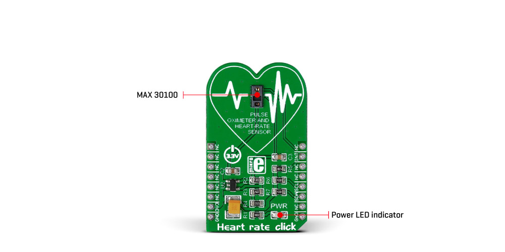
This sensor features two integrated LEDs with the RED and IR LEDs, used to emit the respective wavelengths. The wavelengths of these LEDs are 660nm and 880nm, respectively. The reflected light is detected by a red/IR photo-detector element and sampled by a low noise delta-sigma 16bit ADC. The analog front end of the MAX30100 sensor features an Ambient Light Cancellation (ALC) section, which eliminates light pollution of the photo-detector element. The 16bit ADC is filtered by a discrete time filter to prevent 50/60Hz interference and hum. The output sampling frequency can be adjusted from 50Hz to 1kHz. There is also a temperature sensor, which can be utilized to compensate for the changes in the environment and to calibrate the measurements.
The MAX30100 sensor has the FIFO buffer, 16 words deep. The FIFO buffer stores the measured values and it can generate an interrupt when the buffer is full, allowing the host MCU to perform other tasks while the data is collected by the sensor.
The integrated LED drivers are operated with pulses of selectable width: pulses can vary from 200µs to 1600µs. The width of the pulse affects the available ADC bit depth and sample rate. The pulse width of 1600µs will allow maximal resolution of 16 bits with the highest sample rate of 1 ksps, while the pulse width of 200µs will only allow 100 sps for 16 bits resolution. Reducing the resolution to 13 bits will allow the full sample rate speed of 1ksps. Control of the LED pulse width, along with the programmable LED current, allows for an optimization of the measurement precision and power consumption. The power supply for the LEDs is taken directly from the 3.3V rail of the mikroBUS™.
To improve the measurements, the MAX30100 sensor employs a temperature sensor. This is a reasonably precise temperature sensor, which measures the die temperature with the accuracy of ±1˚C in the range of -40˚C to +85˚C. This sensor can be read from its data register and can be optionally used to compensate the sensor readings to the environmental temperature fluctuations. However, several other external factors can affect the precision of the device: besides the temperature, readings can be negatively affected by the excess motion, too. Also, too much pressure can constrict capillary blood flow and therefore diminish the reliability of the data. Those problems arise from the nature of the measurement method and should be considered while developing own application.
The MAX30100 sensor is supplied by the small LDO, which outputs clean and ripple free 1.8V for the internal logic and photo-detector element of the sensor. The input voltage is also taken from the 3.3V power rail of the mikroBUS™.
Besides the I2C lines of the sensor IC, routed to the respective mikroBUS™ SCL and SDA lines, the interrupt line from the sensor is also routed to the mikroBUS™ INT pin. By setting the appropriate INT register, the interrupt can be generated and enabled for 5 different sources: power ready, SpO2 ready, HR ready, temp ready, FIFO full. The power ready interrupt is enabled by default and can’t be disabled in software, but all other interrupts can be disabled or enabled, depending on the requirements of the application. Each interrupt is reported by the status bit in the interrupt status register and by pulling the INT line to a LOW logic state. The INT line is an open-drain, so it is pulled up to the HIGH logic level by the onboard resistor.
The extensive information for the MAX30100 sensor and its registers can be obtained from the MAX30100 datasheet. However, the provided library offers simple and easy to use functions, used to configure the device and measure the SpO2 and HR properties of the human body. Those functions are demonstrated in the included application example, which can be used as a reference for a custom design.
Specifications
Type Biometrics,Heart Rate Applications Developing algorithms for pulse oximetry and heart rate readings through the tip of a finger On-board modules Maxim’s MAX30100 integrated pulse oximetry and heart-rate sensor Key Features Optical sensor: IR and red LED combined with photodetector. Measures absorbance of pulsing blood Interface I2C Compatibility mikroBUS Click board size M (42.9 x 25.4 mm) Input Voltage 3.3V
Pinout diagram
This table shows how the pinout on Heart rate click corresponds to the pinout on the mikroBUS™ socket (the latter shown in the two middle columns).
| Notes | Pin | Pin | Notes | ||||
|---|---|---|---|---|---|---|---|
| NC | 1 | AN | PWM | 16 | NC | ||
| NC | 2 | RST | INT | 15 | INT | ||
| NC | 3 | CS | TX | 14 | NC | ||
| NC | 4 | SCK | RX | 13 | NC | ||
| NC | 5 | MISO | SCL | 12 | SCL | I2C clock | |
| NC | 6 | MOSI | SDA | 11 | SDA | I2C data | |
| Power supply | +3.3V | 7 | 3.3V | 5V | 10 | NC | |
| Ground | GND | 8 | GND | GND | 9 | GND | Ground |
Onboard jumpers and settings
| Label | Name | Default | Description |
|---|---|---|---|
| LD1 | PWR | LED | Power LED indicator |
Software support
We provide a library for Heart rate click on our Libstock page, as well as a demo application (example), developed using MikroElektronika compilers and mikroSDK. The provided click library is mikroSDK standard compliant. The demo application can run on all the main MikroElektronika development boards.
Library Description
The library carries all functionalities of the Heart rate click.
Key functions:
uint8_t heartrate_readIrRed(uint16_t *ir_buff, uint16_t *red_buff );- This function reads IR and RED values.void heartrate_init();- This function restarts and initializes the Heartrate chip.uint8_t heartrateDataReady()- This function checks if the data is ready for reading.
Examples Description
- System Initialization - Initializes GPIO INT as the input pin, I2C, and UART for logging.
- Application Initialization - Initializes heartrate driver and Click board™.
- Application Task - reading the value from both Ir and Red diode displaying their average values.
void applicationTask(){ if (heartrateDataReady()) { sample_num = heartrate_readIrRed( &ir_buff, &red_buff ); if ( sample_num >= 1 ) { ir_average = 0; red_average = 0; for ( counter1 = 0; counter1 < sample_num; counter1++ ) { ir_average += ir_buff[counter1]; red_average += red_buff[counter1]; } ir_average /= sample_num; red_average /= sample_num; counter2++; if(counter2 > 100) { mikrobus_logWrite("Average value of Red LED sensor per 100 samples:",_LOG_TEXT); WordToStr(red_average, text); mikrobus_logWrite(text,_LOG_LINE); mikrobus_logWrite("Average value of IR LED sensor per 100 samples:",_LOG_TEXT); WordToStr(ir_average, text); mikrobus_logWrite(text,_LOG_LINE); counter2 = 0; } } }}The full application code, and ready to use projects can be found on our Libstock page.
Other mikroE Libraries used in the example:
- UART
- Conversions
- I2C
Additional notes and information
Depending on the development board you are using, you may need USB UART click, USB UART 2 click or RS232 click to connect to your PC, for development systems with no UART to USB interface available on the board. The terminal available in all MikroElektronika compilers, or any other terminal application of your choice, can be used to read the message.
mikroSDK
This click board is supported with mikroSDK - MikroElektronika Software Development Kit. To ensure proper operation of mikroSDK compliant click board demo applications, mikroSDK should be downloaded from the LibStock and installed for the compiler you are using.
For more information about mikroSDK, visit the official page.
Shipping rates Australia wide and New Zealand
FAQ:
- How do I estimate shipping for my order?
- Add products in the shopping cart and head to the checkout page to estimate the shipping.
Dispatch time
Unless expressly agreed otherwise with you, we will not commence delivery of an order until we have received cleared payment of the purchase price in full.
All orders placed before 11 am AEST (Monday to Friday) will ordinarily be processed on the same day.
We will endeavour to ship the Products by the applicable time indicated on the website, but all times are indicative only. All shipping times are dispatch times only, and actual delivery dates will depend on the shipping method chosen, delivery address and delivery service provider.
Note- Please make a note during purchase if you require any item urgently. However we cannot guarantee that we will be able to comply with any request.
*Go to Australia post delivery time calculation to get various Australia post service in your area please use our shipping postcode Thomastown, 3074 as the "from" address - https://auspost.com.au/parcels-mail/delivery-times.html?ilink=tools-open-deliv-times.
We ship all products throughout mainland Australia, Tasmania and New Zealand - Including Darwin, Melbourne, Sydney, Tasmania, Adelaide, Brisbane, Perth, all metro and regional areas but do not deliver to areas in Australia where the Australia Post delivery network is not available.
Check Express shipping delivery coverage area at - http://auspost.com.au/parcels-mail/delivery-areas.html
Receipt of deliveries
Deliveries to post office boxes are not permitted where delivery is by courier. If delivery is by courier and nobody is available at the delivery address to accept delivery when delivery is attempted then the courier may either:
- leave the relevant parcel at the unattended address (the courier will do so if specified in your delivery requirements); or
- re-attempt delivery at a later time or date, in which case we may charge you an additional re-delivery fee.
Note that if a delivery is left unattended at the shipping address and is subsequently stolen then the theft is your responsibility, not ours.
Payment & Security
Your payment information is processed securely. We do not store credit card details nor have access to your credit card information.